So, a 52/3150 Transformer Bushing is basically a high-voltage interface used in transformers. When you see the number 52 or 3150, it's often pointing to a 52 kV voltage class and a continuous current rating of 3,150 amps. But honestly, that’s just part of the story—there’s more to it. Things like insulation quality, creepage distance, how well it can handle short circuits, the conductor design, and how it’s installed—all matter quite a bit. International standards like IEC 60137:2017 cover the main requirements for bushings above 1,000 volts, and in North America, IEEE C57.19.00-2022 offers useful guidance for these components.
Basically, this part carries current through the transformer tank but still keeps it electrically separated from the grounded metal parts. Think of it like a Porcelain or composite body sticking out of the transformer cover, with a conductor passing right through the center. Inside, condenser layers help control the electric field, ensuring everything stays safe and functional. On the outside, though, things like weather, pollution, moisture, and temperature changes can wear down its performance over time. CIGRE’s Transformer Reliability Survey (Brochure 642) highlights why it’s so crucial to monitor these components and understand what causes failures in the field—because sometimes, a tiny accessory can lead to big outages.
Now, just knowing the rating isn’t enough. You can't just assume it’s good to go based solely on those numbers. Engineers really need to double-check how it fits into your system—things like voltage levels, max operating current, lightning impulse levels, oil compatibility, terminal sizes, and diagnostic needs. Also, real-world experience shows that loose connections or poor seals can create hot spots, partial discharges, or even leaks, which can cause serious problems. These small details are often overlooked but can make a huge difference.
In this overview, we’ll dig into the structure, ratings, uses, testing methods, and maintenance tips for this kind of bushing. And we’ll also chat about one common shortcut people take—treating every 52 kV, 3,150 A bushing as interchangeable. Spoiler: they’re not. Each one has its own quirks and specific requirements, so don’t assume you can swap them out without proper checks.
Definition and Meaning of the 52/3150 Transformer Bushing
What Is a 52/3150 Transformer Bushing?
Definition and Meaning of the 52/3150 Transformer Bushing
A 52/3150 Transformer Bushing is a high-voltage interface for connecting a transformer winding to an external conductor. The number 52 usually indicates a maximum system voltage of 52 kV. The number 3150 indicates a rated continuous current of 3,150 amperes. It is not merely a large porcelain tube. The bushing must control electric stress, carry heat, and withstand mechanical forces during service.
IEC 60137 defines key requirements for insulated bushings above 1 kV, including insulation tests, temperature-rise limits, and partial-discharge verification. IEEE C57.19.00 provides additional application guidance for transformer bushings. Industry reliability surveys published through CIGRE repeatedly identify bushings as important contributors to transformer outages. That finding deserves attention. A high current rating does not guarantee reliable operation.
During inspection, engineers check oil level, sealing surfaces, terminal temperature, capacitance, and tan delta. A loose connection can create a small hot spot, like a darkened bolt inside a bright metal terminal. Moisture may increase dielectric losses slowly. The change can look harmless at first.
The designation Dt 3/3150 Transformer Bushing may describe a related design or drawing code, not an equivalent product. Never assume the markings match automatically. I would verify the rated voltage, insulation level, creepage distance, mounting dimensions, and test certificates before approval. This step is easy to overlook. It should not be.
What Is a 52/3150 Transformer Bushing?
The designation “52/3150” identifies two key electrical ratings of a transformer bushing: a rated voltage of 52 kV and a rated current of 3150 A.
The 52 kV rating indicates the maximum system voltage class for which the bushing is designed, while the 3150 A rating indicates the continuous current it can carry under specified operating conditions.
Key Electrical Ratings and Performance Specifications
What Is a 52/3150 Transformer Bushing?
A 52/3150 transformer bushing usually identifies a 52 kV voltage class and a 3,150 A continuous current rating. The notation is compact, but it does not describe every performance limit. Actual specifications may include power-frequency withstand, lightning impulse withstand, partial-discharge limits, creepage distance, and temperature rise. These values must match the transformer, insulation system, and installation environment.
A 52 kV bushing may serve a high-voltage transformer connection where insulation coordination is critical. The 3,150 A rating supports heavy continuous loading, but only when cooling conditions are suitable. Contact resistance, conductor size, ambient temperature, and mounting position can affect real performance. During commissioning, engineers typically review factory test reports and inspect sealing surfaces, terminals, and oil or compound levels. A small leak matters. So does an overlooked loose connection.
Tips
Confirm whether 52 kV means the rated voltage or the highest system voltage. Check the required impulse level instead of assuming it from the label. Compare the bushing’s current rating with expected load, emergency loading, and temperature-rise data. Infrared inspections can reveal a hot terminal before visible damage appears. I would also verify creepage distance for pollution and moisture conditions. That step is sometimes missed, especially when a replacement appears mechanically identical. Specification sheets should be checked against current project standards and the transformer’s insulation coordination study.
Main Components and Internal Construction
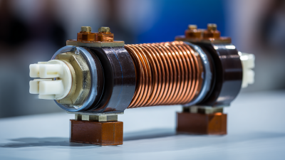
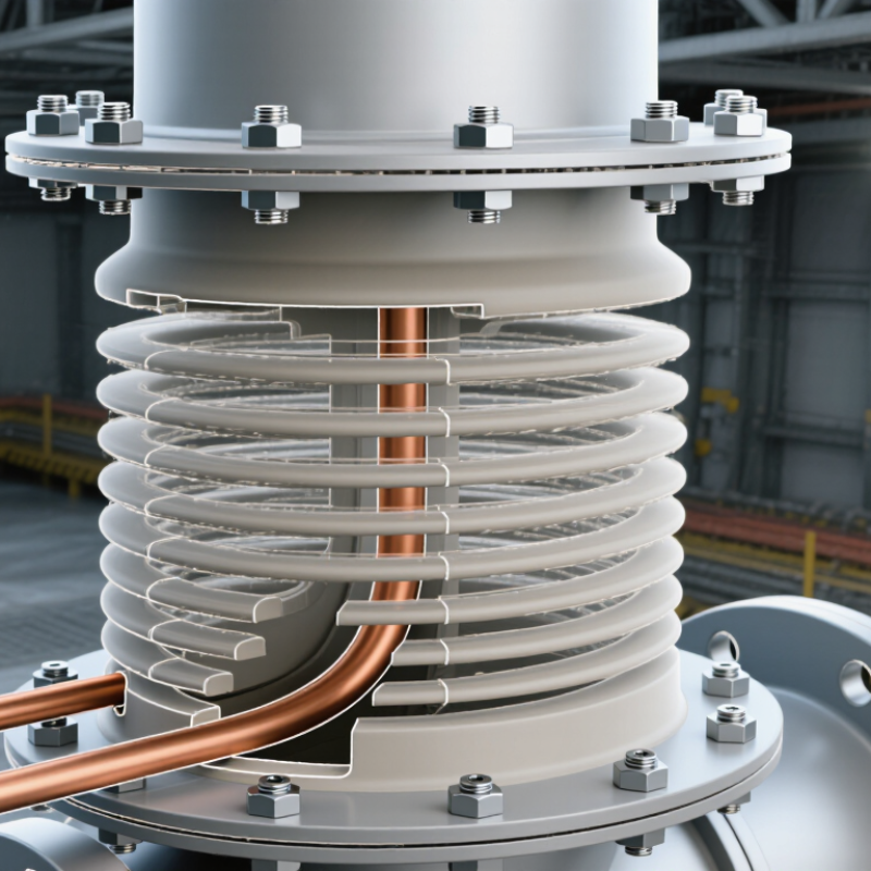
A 52/3150 transformer bushing is designed for a 52 kV system and a continuous current of 3,150 A. It carries current through the transformer tank wall while maintaining electrical insulation. Its internal construction is more important than its external profile. A central conductor connects the winding to the line terminal. Around it, condenser layers control the electric field. These layers usually use alternating conductive foil and insulating paper or polymer film. The graded structure reduces local stress near the flange and conductor.
The bushing body may include oil-impregnated paper, resin-impregnated paper, or solid composite insulation. A porcelain or polymer housing provides outdoor creepage distance. Sealing elements prevent moisture from entering the insulation system. Many designs also include a test tap for capacitance and dissipation-factor measurements. IEC 60137 defines key requirements for insulated bushings. CIGRE Technical Brochure 642 reviewed 964 transformer failure records and identified insulation-related defects as important failure contributors. That figure deserves attention. A small seal problem can develop into internal discharge, although field conditions vary.
Tips: Check capacitance and tan delta against factory or commissioning values. Inspect the test tap cover, flange seals, oil level, and terminal temperature. Thermal imaging can reveal loose connections before visible damage appears. Do not judge condition from appearance alone. Maintenance records are often incomplete, and that is a practical weakness. Record ambient temperature, load current, and test voltage during every inspection.
How the Bushing Operates in a Power Transformer
What Is a 52/3150 Transformer Bushing?
How the Bushing Operates in a Power Transformer
A 52/3150 transformer bushing commonly indicates a 52 kV insulation class and a 3,150 ampere continuous current rating. The exact designation can vary by technical standard. I would not treat the label alone as a complete specification.
Inside the power transformer, the bushing carries current through a solid central conductor. Its insulation separates that conductor from the grounded tank wall. The upper section works in outdoor air, while the lower section extends into transformer oil. This sealed transition prevents dangerous flashover at the tank opening. It also keeps moisture away from the internal insulation.
Electric field control is equally important. Many bushings use layered insulation with carefully arranged conductive screens. These layers spread voltage stress instead of allowing it to concentrate at one sharp point. Some designs include a test or capacitance tap for insulation checks. During operation, the conductor produces heat, especially near full load. The bushing must transfer that heat through metal parts and surrounding air or oil.
In field inspections, technicians examine oil leaks, cracked porcelain, loose connections, and unusual temperature rise. A Dt 1/3150 Transformer Bushing may appear clean outside but still contain internal insulation damage. That is the difficult part. Surface condition cannot prove electrical health. Moisture, aging, and poor installation can change performance quietly, so testing and torque verification deserve careful attention.
Common Applications in High-Voltage Equipment
What Is a 52/3150 Transformer Bushing?
Common Applications in High-Voltage Equipment
A 52/3150 transformer bushing is an insulated passage for carrying electrical current through a grounded transformer tank. The designation commonly suggests a 52 kV voltage class and a 3150 A current rating. However, engineers should confirm the manufacturer’s drawings and applicable standard before installation. Similar markings can vary between specifications.
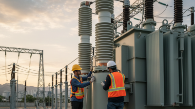
These bushings are widely used in power transformers at substations, generating stations, and heavy industrial facilities. They connect internal windings to overhead conductors, busbars, or cable systems. A 3150 A rating suits high-load transformer terminals where heat management is critical. The bushing’s conductor, insulation, flange, and sealing system must work together under electrical and mechanical stress.
Outdoor transformer yards often use porcelain or composite housings with extended creepage distances. These surfaces help resist moisture, dust, and salt contamination. Indoor switchgear rooms may require different dimensions and shielding arrangements. A practical inspection includes checking oil levels, terminal connections, gasket compression, and signs of partial discharge.
The term Din 42539 3/3150 Transformer Bushing may appear in procurement documents or replacement discussions. It should not be treated as a complete compatibility guarantee. Interface dimensions, impulse withstand levels, insulation coordination, and mounting details still need verification. I have seen projects delayed by one overlooked flange measurement. Small errors become expensive quickly. Temperature rise tests and site conditions also deserve careful review.
Installation, Inspection, and Maintenance Requirements
What Is a 52/3150 Transformer Bushing?
A 52/3150 transformer bushing is designed for high-voltage transformer connections. The “52” commonly indicates a 52 kV class, while “3150” refers to a 3,150 ampere current rating. Confirm these values against the nameplate and approved drawings. Do not rely on appearance alone. A Din 42530 1/3150 Transformer Bushing may have different dimensions, interfaces, or insulation requirements. Always verify the exact specification before installation.
Installation must begin with isolation, grounding, and documented safety procedures. Inspect the porcelain or composite body for cracks, chips, moisture, and contamination. Check the conductor, flange, seals, and connection hardware. The mounting surface must be clean and level. Tighten fasteners evenly, using the specified torque. Excessive force can damage seals or distort the flange. It happens more often than expected.
Before energizing, test insulation resistance and confirm electrical clearances. Check terminal alignment and verify that no tools remain inside the transformer. During service, inspect for oil leaks, corrosion, discoloration, unusual noise, or local heating. Infrared scanning can reveal a loose connection before visible damage appears. Record readings and compare them with earlier results. A checklist helps, but it is not perfect. Recheck unusual results, especially after transport, severe weather, or maintenance work.
DIN 42532 10NF3150 Porcelain Insulator: Reliable Transformer Applications and Selection Guide
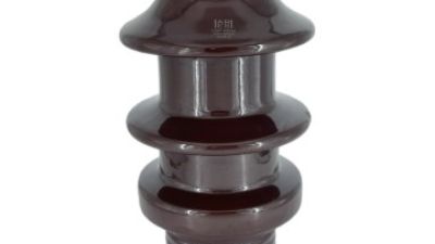
The DIN 42532 10NF3150 porcelain insulator is designed for dependable transformer applications in voltage power transmission and distribution systems. Manufactured from high-quality porcelain material, it provides stable electrical insulation and reliable mechanical support under demanding operating conditions. Its robust construction makes it suitable for transformer bushing and related high-voltage equipment where consistent performance, durability, and safe electrical separation are essential.
When selecting this insulator, engineers should verify the transformer’s rated voltage, installation configuration, creepage requirements, mechanical loading, and compatibility with the surrounding fittings. Environmental conditions such as humidity, pollution, temperature changes, and outdoor exposure should also be considered to ensure long-term service reliability. The DIN 42532 10NF3150 model is produced in Jiangxi, China, and is supported by ISO9001 certification and type-test verification, providing useful quality references for procurement and technical evaluation.
FAQS
It usually indicates a 52 kV voltage class and a 3,150 ampere continuous current rating. The label is not a complete specification. Check the applicable technical standard.
It carries current through a central conductor. Insulation separates the conductor from the grounded transformer tank. The upper section operates in air, while the lower section enters transformer oil.
It limits electrical stress during normal operation and surges. Engineers should check power-frequency withstand and lightning impulse withstand levels. Do not assume these values from the voltage label.
No. Cooling, conductor size, contact resistance, ambient temperature, and mounting position affect actual performance. Temperature-rise data deserves close attention. Ratings need suitable conditions.
Review factory test reports and inspect terminals, sealing surfaces, and oil or compound levels. Verify connection torque carefully. A loose connection can create dangerous heating.
Inspect for oil leaks, cracked porcelain, loose terminals, and unusual temperature rise. Infrared scanning can reveal a hot connection early. Small leaks matter.
Yes. Moisture, aging, and poor installation may damage internal insulation without obvious surface marks. Exterior appearance cannot prove electrical health. Test it properly.
Check creepage distance for pollution and moisture conditions. Consider the installation atmosphere, expected loading, and emergency loading. A mechanically identical replacement may still be electrically unsuitable.
Some designs include conductive screens and a test or capacitance tap. These features help control electric fields and support insulation checks. Their use depends on the design.
Compare the specification sheet with project standards and the transformer’s insulation coordination study. Confirm voltage meaning, impulse levels, current capacity, and temperature rise. Check it twice.
Conclusion
A 52/3150 Transformer Bushing is a high-voltage insulating component designed to provide a safe, controlled path for an energized conductor to pass through a transformer tank or enclosure. The designation generally identifies its rated voltage class and continuous current capacity, while its performance depends on insulation strength, temperature stability, leakage control, and resistance to electrical and mechanical stress. Its main construction typically includes a central conductor, solid or layered insulation, shielding elements, a mounting flange, sealing parts, and external connection terminals.
During transformer operation, the bushing transfers electrical current between internal windings and external power equipment while maintaining isolation from the grounded tank. It is commonly used in substations, transmission systems, and other high-voltage equipment. Proper installation requires correct alignment, secure connections, clean insulating surfaces, and effective sealing. Regular inspection should check for cracks, contamination, oil or gas leakage, overheating, corrosion, and abnormal electrical test results. Preventive maintenance helps preserve reliability, reduce insulation failure risks, and extend the service life of the transformer system.